
This blog post outlines flag 3 of the Nestadia reverse engineering track, a cloud-based gaming platform for the NES inspired by Google stadia.
Welcome back to my mini-series on the NorthSec 2021 Nestadia challenge track. This time around, we are about to dive deep into NES internals to craft a malicious ROM and attack the Nestadia server. I hope you’re ready for this wild ride. If you haven’t read the first part, make sure to head over there and read it first, as this post is a direct continuation.
Before getting into the writeup, I want to give a big shout out to @zer0x64, the designer of the track, and to my PauMd teammate Kafka for the super clutch submission with exactly 8 seconds to go before the CTF ended. This flag was worth a huge 6 points and was the culmination of me frantically reversing Rust, learning 6502 assembly, NES internals and how to use the PPU to draw tiles on the screen to leak memory through a graphics only interface.
Locating the Remaining Flags
After that stint in ROM reversing, it’s fairly obvious that the carved ROMs no longer serve a purpose and that we’ll likely not find the third flag in any of them, including the development ROM.
Well, that can only mean one thing, it’s time to look at the server binary in more depth. There must be some flags somewhere in the binary…
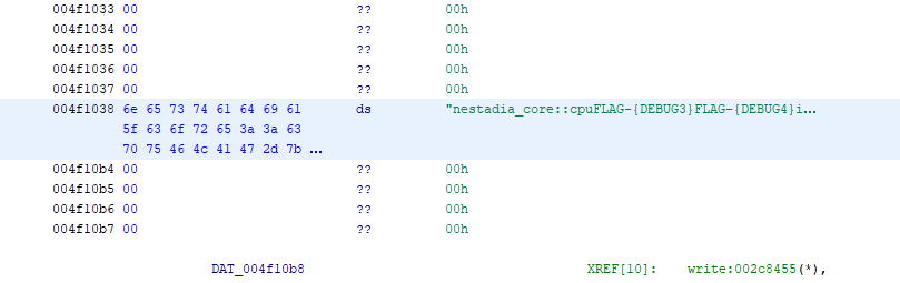
Let’s run a quick strings and see if we can find any information:
dom0@th1nk NSEC21/nestadia/www $ strings nestadia_debug | grep 'FLAG-{'
[...]
nestadia_core::cpuFLAG-{DEBUG3}FLAG-{DEBUG4}internal error: [...]
As expected, both remaining flags are inside the binary, however, they
are bunched up together among a few other strings. This is because the
Rust compiler pools static strings into a single (well, several, to be
precise) large contiguous strings. The reason this is done is that in
Rust, strings do not need to be null terminated, as a string is
effectively a (ptr, len) tuple.
To make it easier, the strings can be manually declared as char[N]
arrays in Ghidra. This makes cross-references to strings easier to
identify and it also cleans up the decompilation by automatically
labelling string pointers. Unfortunately, after doing that, it still
looks like there are no cross-references to those two strings, making
it difficult to know where they are being used.
At this point, there are a few possible ideas:
- The flag is somewhere in CPU memory and the memory must be leaked
- There is an uncodumented (sequence of) instructions which will retrieve the flag
- The emulator has a bug that lets us read arbitrary memory
- We have to perform a Sandbox escape from the emulator
The only way to interact with the server other than through its web API is by uploading a ROM, meaning that we essentially already have “arbitrary” code execution in the NES “sandbox”.
In all scenarios, we will need to exfiltrate some memory via the ROM, so in any case, let’s figure out how exactly to build NES games!
Thankfully, NESDevWiki has a huge amount of resources on NES homebrew development. Let’s grab an example ROM, install the c65 toolchain and we’re off to the races.
I won’t go into detail about how to setup and compile NES ROMs to keep the writeup length reasonable. I will provide relevant details as needed to follow along with the writeup.
The first thing to do is to build the example ROM and load it in FCEUX to prove that everything is working. Once that’s confirmed, loading it into Nestadia verifies that the cloud-based emulator can also read the ROM fine.
All set! Time to learn 6502 if we’re going to leak the memory…
The 6502 Architecture
The 6502 processor is a relatively simple RISC instruction set. It has
only 3 usable registers: A, X and Y, along with the usual PC,
SP and EFLAGS, which are respectively called PC, S and P.
All registers are 8 bits wide, except PC, which is 16 bits to cover
the 16 bit addressable space. The processor uses a page known as the
zero-page (ZP) which consists of 256 bytes (00-FF) that is
index-addressed by several instructions to provide 16 bit addresses or
store state. The ZP is an integral part of efficient 6502 programming.
Several instructions operate implicitly on the values in the A
register, which is known as the accumulator. In fact, the A register
is the only one that can be used for indirect memory operations, with
X and Y serving as indices in the zero-page.
Common instructions are listed below, but the full instruction set can be found here.
| Mnemonic | Description |
|---|---|
LDA |
Load a literal, or memory location into A |
TXA |
Transfer X into A |
STA |
Store the value of A at an indexed location |
CMP |
Compare the value of A against an immediate or memory location |
INX |
Increase the value of X by one |
Data Exfiltration
Since it’s not very useful to read memory if it can’t be analyzed outside of the ROM itself, we need a way to exfiltrate the bytes out of the ROM and emulator. This is true for testing, but it will be even more important once our game is running on the server remotely. We could obviously draw to the game screen, but this is going to be tedious for debugging.
While reading through the iNES format, two things stand out:
-
The header allows to specify various mappers which act as extensions to the NES CPU. We will go over these in more detail soon.
-
A header flag which indicates the presence of a persistent SRAM block in the cartridge that allows save data to be stored.
Interestingly, nestadia_server creates an empty saves/ directory
on the first run. Maybe if we flipped the SRAM flag to true in our
ROM, the memory we write there would be saved to disk? While this
turns out to be the case, attempts to write at that memory location
yield an error in the emulator, complaining that the game attempted to
write to memory marked as read-only.
This is actually because the default mapper (mapper 0) does not support SRAM, so the whole memory space is read-only.
To understand how this works, let’s look at a quick diagram:
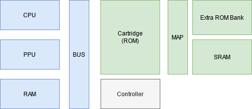
The NES computer is basically made up of these components:
- The CPU is responsible for executing the actual game logic
- The PPU is responsible for drawing the screen
- The RAM is an internal volatile read/write memory for storing game state.
- The BUS is responsible for connecting the CPU, the PPU, and the game cartridge.
The cartridge and game controllers (joypads) connect directly to the BUS and are also mapped to the available memory space.
These connections are made through a memory mapping, in other words, the memory space is divided into well-known chunks that map to the right components of the NES. Mappers are on-cartridge extensions that further segment the memory that normally belongs to the cartridge ROM so that writes to a portion of it goes through the mapper and into the cartridge extensions. These extensions are most commonly used in conjunction with bank registers to provide more storage space for game resources.
All of this to say that according to NesDevWiki, Mapper 1 is a mapper
which supports SRAM. So after modifying the lower nibble of the
mapper flag in the iNES Header, suddenly writes to 6000-7FFF (the
SRAM location) start showing up in the .save file.
The next hour or two were spent playing with all possible mappers and dumping all inernal CPU RAM and uninitialized mapper spces to SRAM in hopes to find the flag. Unfortunately, this also did not give up any flags.
Reverse Engineering the Emulator CPU
Enough rabbit holes, let’s get on with the part that should’ve been
the very first step (hindsight is 20-20, as the saying goes). Thanks
to the symbols, we know there is a function called
nestadia_core::cpu::Cpu::clock which sounds like it might be
responsible for ticking the CPU clock. Let’s start reversing from there.
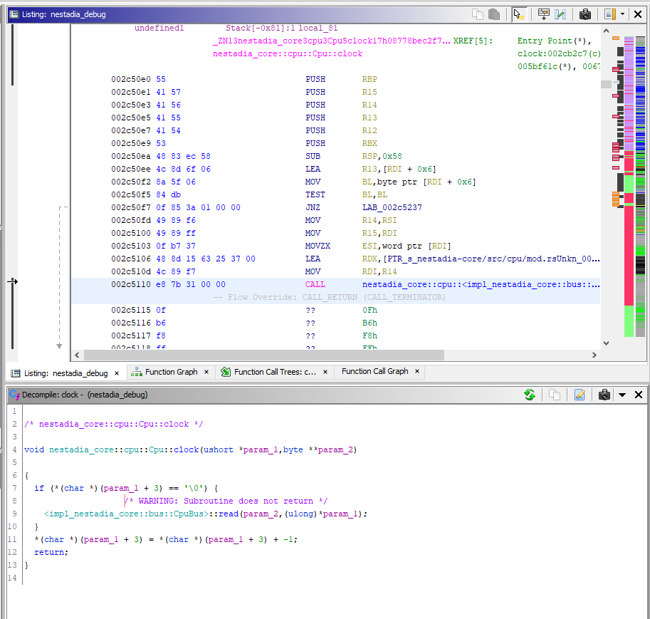
Looking at the listing, this is a relatively straight forward
function, but Ghidra’s default analyzer seems to break on the first
call to a function called bus::read which sounds like it’s
responsible for reading memory from the cartridge. This is to be
expected, as the CPU must read an opcode at PC to get anything done.
After a bit of digging, the reason this happens is because the read
function has a panic! macro in it to handle invalid memory reads,
causing Ghidra’s analysers mistakenly mark the function as noreturn.
This can easily be fixed by editing the function signature to remove
the no-return, clearing the disassembled bytes, and disassembling a
second time. Unfortunately, this is something that will have to be
done multiple times to get good decompilations.
At last, some actual reverse engineering! There’s a lot more stuff
going on here. The first part immediately after the prologue is reading
the memory bus, at what we can safely guess to be PC, and retrieving
one byte (this can be inferred because of the MOVZX EDI, AL which
zero-extends the 8 bit value inside AL into 32 bit wide EDI.
The value in EDI is the sent through OpCode::TryFromPrimitive and if the conversion works,
some processing is done by adding 0x80 to the byte that was read from PC.
NOTE: It is not shown here, but
TryFromPrimitiveputs the return value inEDX’s lower 8 bits and returns the success indicator inAL.
Next, we hit a small road block: A pointer to a large dispatch table
is loaded in RDX and the value of the opcode (now in ECX is used
as an index into that table. The handler address is computed as
dispatch + dispatch[opcode] and an indirect jump is performed.
Unfortunately, Ghidra refuses to analyze the jump table as it is too
large.
Everybody knows that a RE challenge is never complete if it doesn’t involve emulation, so let’s write a script to emulate the calculation and automatically annotate each handler to easily locate them. We know the index is only 8 bits, so we just write the following bruteforce Ghidra script:
import ghidra.app.script.GhidraScript;
import ghidra.program.model.address.Address;
import ghidra.program.model.lang.Register;
import ghidra.program.model.listing.Instruction;
import ghidra.program.model.symbol.FlowType;
import ghidra.program.model.symbol.SourceType;
import ghidra.util.Msg;
import paa.emulation.EmulationContext;
import paa.emulation.IEmulationCallback;

public class JumpTable extends GhidraScript {
    @Override
    protected void run() throws Exception {
        var emu = EmulationContext.New(currentProgram, monitor)
                  .withStackSize(0x1000)
                  .build();
        var rcx = currentProgram.getLanguage().getRegister("RCX");
        // "Bruteforce" emulate each switch case and add a bookmark at the jump target
        for (var i = 0; i <= 255; i++) {
            emu.getEmulator().getMemState().setValue(rcx, i);
            emu.run(currentAddress, 3);
            var va = emu.getEmulator().getMemState().getValue(rcx);
            println(String.format("Opcode %02X: %016x", i, va));
            var addr = currentProgram.getAddressFactory()
                                     .getDefaultAddressSpace()
                                     .getAddress(va);
            var st = currentProgram.getSymbolTable();
            var label = String.format("opcode_%02x", i);
            st.createLabel(addr, label, SourceType.USER_DEFINED);
        }
    }
}
NOTE: This script uses some of my personal emulation framework built on top of Ghidra. This can still be done with vanilla Ghidra, but will require a full rewrite.
Running the script results in a new label being created at each opcode
handler, making it easy to manually fix the disassembly that Ghidra
missed or improperly annotated. The process is quite simple: Start
disassembly from the label, and any time there is conflicting code
that Ghidra has mistakenly disassembled, clear it and continue from
the last good instruction. As soon as opcode_00 is disassembled,
however, luck strikes:
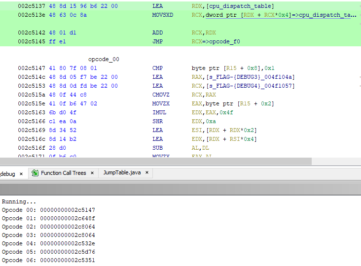
It’s the missing XREFs to the flag!! By now there are about two hours left in the CTF, and the clock is ticking. How is this opcode triggered, where does it put the flag, what does it do? How do we use it? So many questions, so little time!
void opcode_00(undefined *cpu)
{
  char *flag;
  char *pCycles;
  char counter;

  flag = "FLAG-{DEBUG4}";
  if (cpu[8] == '\x01') {
    flag = "FLAG-{DEBUG3}";
  }
  cpu[2] = flag[(byte)cpu[2] % 0xd]; // len("FLAG-{DEBUG3}") == 0xD
  counter = *pCycles;
  *pCycles = counter + '\x04';
  *pCycles = counter + '\x03';
  return;
}
We know that the instruction to trigger this opcode is hex((0x00 - 0x80) & 0xFF) == 0x80, so let’s start there.
The code appears to read a value at r15 + 2, treat it as an index
into the flag array, and write the byte at that position back into
r15 + 2. The most likely explanation for this is that r15 is the
CPU state and offset 2 is one of the registers. There’s only one way
to find out.
Figuring out the CPU State
The idea is simple, but time is short: Build a ROM with a single LDx
instruction and see where the value is stored by setting a breakpoint
on the jmp rcx dispatcher.
The ROM, based on the example ROM and replacing the reset function,
goes like this:
.segment "HEADER"
INES_MAPPER = 0 ; 0 = NROM
INES_MIRROR = 1 ; 0 = horizontal mirroring, 1 = vertical mirroring
INES_SRAM   = 0 ; 1 = battery backed SRAM at $6000-7FFF
.byte 'N', 'E', 'S', $1A ; MAGIC
.byte $02 ; 16k PRG chunk count
.byte $01 ; 8k CHR chunk count

; ROM flags
.byte INES_MIRROR | (INES_SRAM << 1) | ((INES_MAPPER & $f) << 4)
.byte (INES_MAPPER & %11110000)
.byte $0, $0, $0, $0, $0, $0, $0, $0 ; padding

.SEGMENT "CODE"
reset:
    lda #65  ; put 0x41 in A
    jmp reset ; loop so we can debug easily
nmi: ; Bogus interrupt handlers that go straight to `reset`
irq:
    jmp reset

.SEGMENT "OAM"
.byte $0
.SEGMENT "VECTORS"
.word nmi ; NMI interrupt handler
.word reset ; reset interrupt handler
.word irq ; IRQ interrupt handler
.SEGMENT "TILES"
Let’s compile it…
ca65 -o lda.o lda.s && ld65 -C example.cfg -o lda.rom lda.o
Next, debug the server and input the magical commands:
pwndbg> set args -b 0.0.0.0
pwndb> r
[...]
^C
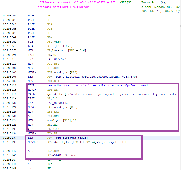
pwndbg> b nestadia_core::cpu::Cpu::clock
Breakpoint 1 at 0x5555557190e0
pwndbg> pd 0x5555557190e0 20
► 0x5555557190e0 <nestadia_core::cpu::Cpu::clock> push rbp
0x5555557190e1 <nestadia_core::cpu::Cpu::clock+1> push r15
0x5555557190e3 <nestadia_core::cpu::Cpu::clock+3> push r14
0x5555557190e5 <nestadia_core::cpu::Cpu::clock+5> push r13
[...]
0x555555719122 <nestadia_core::cpu::Cpu::clock+66> movzx eax, word ptr [r15]
0x555555719126 <nestadia_core::cpu::Cpu::clock+70> mov esi, eax
0x555555719128 <nestadia_core::cpu::Cpu::clock+72> add esi, 1
0x55555571912b <nestadia_core::cpu::Cpu::clock+75> mov word ptr [r15], si
0x55555571912f <nestadia_core::cpu::Cpu::clock+79> mov bl, 2
0x555555719131 <nestadia_core::cpu::Cpu::clock+81> add dl, 0x80
0x555555719134 <nestadia_core::cpu::Cpu::clock+84> movzx ecx, dl
0x555555719137 <nestadia_core::cpu::Cpu::clock+87> lea rdx, [rip + 0x22b696]
; compute opcode handler address
0x55555571913e <nestadia_core::cpu::Cpu::clock+94> movsxd rcx, dword ptr [rdx + rcx*4]
0x555555719142 <nestadia_core::cpu::Cpu::clock+98> add rcx, rdx
; dispatch to handler
0x555555719145 <nestadia_core::cpu::Cpu::clock+101> jmp rcx
pwndbg> bd 1
pwndbg> b *0x555555719145
Breakpoint 2 at 0x555555719145
pwndbg> c
Continuing.
Thread 99 "actix-rt:worker" hit Breakpoint 2, 0x0000555555719145 in nestadia_core::cpu::Cpu::clock ()
LEGEND: STACK | HEAP | CODE | DATA | RWX | RODATA
───[ REGISTERS ]──────────
RBX 0x7ffe967d1402 ◂— 0x0
RCX 0x55555571a677 (nestadia_core::cpu::Cpu::clock+5527) ◂— lea rdx, [rip + 0x3718b2]
RDX 0x5555559447d4 ◂— 0xffdd5cbbffdd4973
RDI 0xa9 <-------- 6502 instruction 0xa9 is at index 0x29
RSI 0x8001
R8 0x7ffe967e0669 ◂— 0x0
R9 0x7ffe967e066a ◂— 0x0
R10 0x2
R11 0x3
R12 0x0
R13 0x7ffe967d152e ◂— 0x12400
R14 0x7ffe967d1320 —▸ 0x7ffe967e0664 ◂— 0x0
R15 0x7ffe967d1528 ◂— 0x2400fd0000008001
RBP 0x7ffe967e0e6a ◂— 0x0
RSP 0x7ffe967d1290 ◂— 0x0
RIP 0x555555719145 (nestadia_core::cpu::Cpu::clock+101) ◂— jmp rcx
pwndbg> pd 0x55555571a677
► 0x55555571a677 <nestadia_core::cpu::Cpu::clock+5527> lea rdx, [rip + 0x3718b2]
0x55555571a67e <nestadia_core::cpu::Cpu::clock+5534> mov rdi, r14
0x55555571a681 <nestadia_core::cpu::Cpu::clock+5537> call 0x55555571c290
0x55555571a686 <nestadia_core::cpu::Cpu::clock+5542> add word ptr [r15], 1
0x55555571a68b <nestadia_core::cpu::Cpu::clock+5547> mov byte ptr [r15 + 2], al
0x55555571a68f <nestadia_core::cpu::Cpu::clock+5551> mov cl, byte ptr [r15 + 7]
pwndbg> until *0x55555571a68f
0x55555571a686 <nestadia_core::cpu::Cpu::clock+5542> add word ptr [r15], 1
0x55555571a68b <nestadia_core::cpu::Cpu::clock+5547> mov byte ptr [r15 + 2], al
► 0x55555571a68f <nestadia_core::cpu::Cpu::clock+5551> mov cl, byte ptr [r15 + 7]
pwndbg> hexdump $r15
+0000 0x7ffff4dd5528 01 80 41 00 00 fd 00 24 01 00 00 00 00 00 28 00 │..A.│...$│....│..(.│
+0010 0x7ffff4dd5538 00 00 00 00 00 00 00 00 00 00 00 00 00 00 00 00 │....│....│....│....│
Above, we set a breakpoint on Cpu::clock to get its address, printed
the disassembly, and found the jmp rcx instruction, then set a
breakpoint on that. After disabling the first breakpoint, we load the
ROM and when the first instruction runs (LDA #65) We hit
breakpoint 2. Note down the interesting values of each registers, then
continue until the mov byte ptr [r15 + 2], al instruction. This is
already exciting because the offset matches the opcode_00 listing.
As expected, the value of AL turns out to be 0x41 meaning that
this is indeed our LDA #65 instruction, and that r15 + 2 is the
A register. To summarize:
| Register | Value |
|---|---|
RDI |
dispatch table offset (opcode + 0x80) |
RSI |
PC register for the NES |
AL |
The operand for LDA |
R15 + 2 |
A register for the NES |
NOTE: We know
RSIisPCbecauseresetis the first function and the code segment of the ROM starts at0x8000.
Writing a Proof of Concept
It’s now almost 2PM, about an hour left before the CTF is done. The solution is in sight. Let’s whip up a proof of concept with the RAM trick from earlier. My 6502 is extremely bad, I am super stresed and working on too little sleep, but here goes nothing:
.segment "HEADER"
INES_MAPPER = 1 ; 0 = NROM, 1 = SRAM
INES_MIRROR = 1 ; 0 = horizontal mirroring, 1 = vertical mirroring
INES_SRAM   = 1 ; 1 = battery backed SRAM at $6000-7FFF

; ...

.SEGMENT "CODE"
reset:
    LDX #0 ; X is the offset to leak
    LDA #0 ; A = X = 0
loop:
    .byte $80 ; A = flag[X]
    STA $6000, X ; SRAM[X] = flag[X]

    INX ; X++
    TXA ; A = X
    CMP #00 ; Dump 255 bytes to RAM until we rollover.
    BNE loop ; Not done yet.

    done:
    JMP done ; infinite loop

; ...
Compiling… running… checking the .save file…
alex@artesia re/nestadia/src $ cat ../www/saves/*.save
FLAG-{DEBUG3}FLAG-{DEBUG3}FLAG-{DEBUG3}FLAG-{DEBUG3}FLAG-{DEBUG3}FLAG-{DEBUG3}FLAG-{DEBUG3}FLAG-{DEBUG3}FLAG-{DEBUG3}
FLAG-{DEBUG3}FLAG-{DEBUG3}FLAG-{DEBUG3}FLAG-{DEBUG3}FLAG-{DEBUG3}FLAG-{DEBUG3}FLAG-{DEBUG3}FLAG-{DEBUG3}FLAG-{DEBUG3}
FLAG-{DEBUG3}FLAG-{DEB
Oh god! It works!!
Wait… oh no… There’s no way to get the .save file from the production server. We’re missing a graphics
library to print the flag to the screen!
pɯnɐd Super-Clutch
There’s less than 30 minutes left to the CTF, we have a PoC, but no exfilration. As I start working on ripping the Flappy bird ROM’s tilemap to get ASCII in my PoC ROM and writing a screen drawing library, My teammate Kafka is frantically looking for a development ROM with source code that might help.
By the 2:50PM mark, I have a library that can print ONE hexadecimal byte for every key press. A single byte at a time… of a potentially 40 character long flag that we’ll need to unhexlify. There’s no way we’re going to make it.
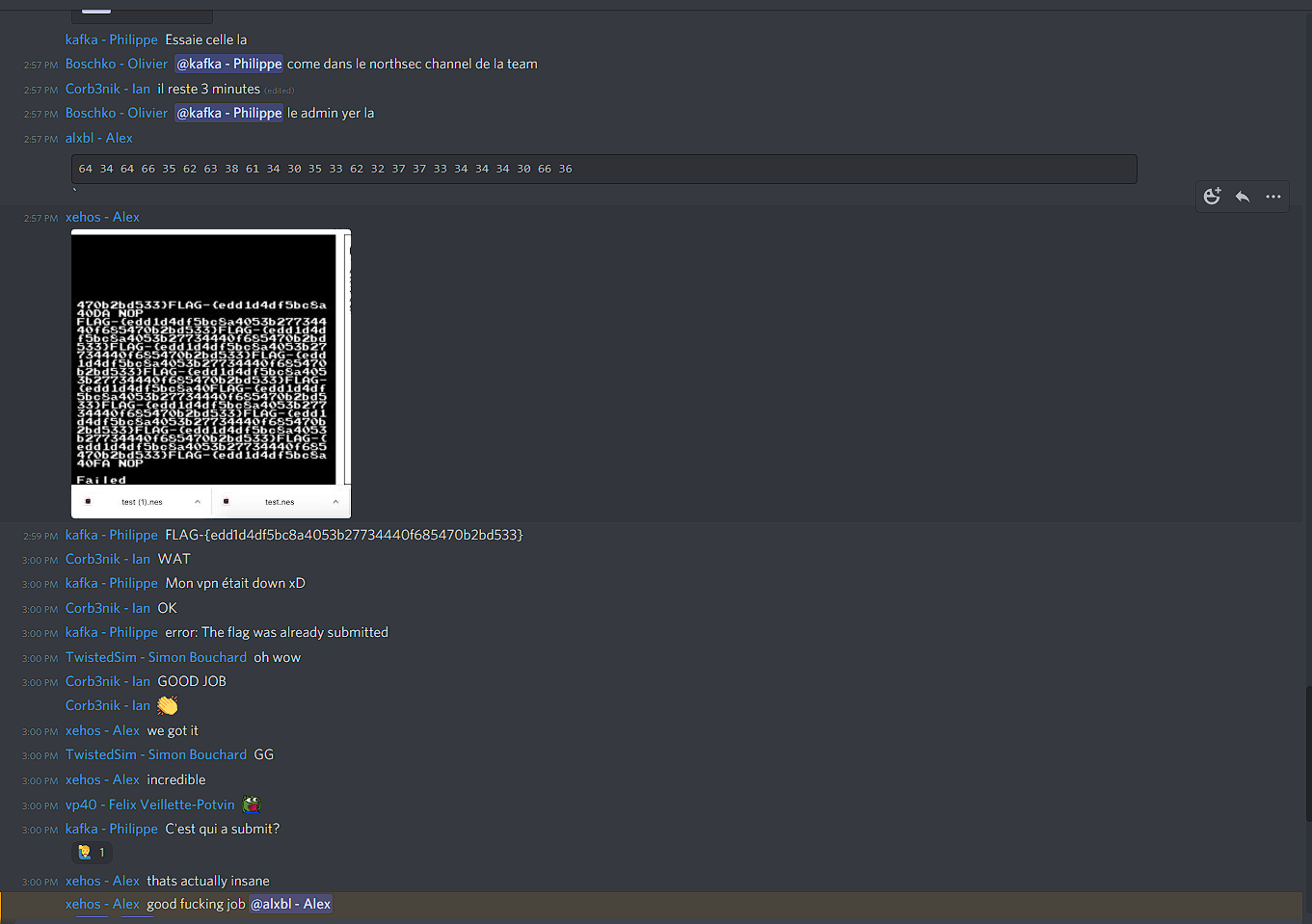
Then Kafka hits me up in Discord with a test.nes and says, “Try this”. I run it locally. All caps time. IT WORKS!
I run it on the server, I get a hexdump of the real flag. In my haste, I accidentally paste it to the NorthSec #CTF channel. I’m jittery, my brain is melting down. I delete the screenshot in panic. I paste it again in our team channel.
5 minutes left. @nitbx, our team leader, is in voice chat with me, I tell him “write this down, be ready to unhex and submit!”
Kafka types “The challenge is down!” He’s not on the CTF VPN, but too panicked to realize. We ping the challenge designer, ticket is opened, everybody is in voice chat freaking out. The ROM is posted.
Another teammate, @xehos, runs the ROM, and posts a screenshot with the flag in plaintext.
1 minute left.
Kafka immediately transcribes the flag into text. I don’t see any of this happening, I’m too busy reciting hexadecimal.
@yol0nline copy pastes the flag and submits it.
Time on the clock: 2:59:52
   98 | swta 2/3 - Debugging   | 3 | 2021/05/23 13:44 | 2/3 - Nice debugging skills you got there
    9 | Avian Carrier 2        | 6 | 2021/05/23 14:26 | UNLEASH THE HORSES!
   55 | Hackers-6              | 1 | 2021/05/23 14:39 | Trust your technolust
   88 | Rune                   | 2 | 2021/05/23 14:39 |
   74 | nestadia 3/4           | 6 | 2021/05/23 14:59 | 3/4 Learning to write NES rom is a very useful skill!
Conclusion
The ROM that ended up working was using a different framework that Kafka found, which contains standard
functions to print text directly to the screen. He replaced 01-implied.s with the following code which blends my PoC with
the ROM’s text printing capability:
.include "shell.inc"
main:
    LDX #0
@loop:
    TXA
    .byte $80
    jsr print_char_
    INX
    BNE @loop
    rts
Despite not having had time to solve the last flag of the track, Kafka and I had a decent idea of how to get the flag. I will likely attempt a solution in the coming weeks, and hopefully have a write up for the full track. On that note, I hope you enjoyed reading this writeup as much as I enjoyed writing it.
Here’s a bit of trivia as well:
- The full track was worth 20 points, with the last flag alone being worth 10.
- PauMd was the only team to solve flag 3.
- PauMd spells
pwnedif you look at it upside down with the right font.